Nondestructive Test Methods for Evaluating Masonry Structures
Have you ever had to convince an inspector that a masonry wall was grouted? Have you ever cut an opening in a wall that was supposed to have been grouted only to find that it was not? Have you ever wondered if the reinforcing specified for a masonry wall or footing was actually installed? If so, how did you answer all of these questions in the past? Banging on face shells with a hammer? Making Swiss cheese out of wall sections with hammer drills and core rigs? There are better ways to address these issues today with better accuracy and less destruction of completed work.
Surface-penetrating radar (SPR) and infrared thermography (IRT) are powerful, nondestructive test methods that aid in the assessment of masonry structures. The testing techniques permit rapid "on-the-spot" evaluation of existing construction conditions and document existing conditions in a portable electronic format.
Masonry Evaluation
SPR and IRT are two methods that have demonstrated advantages in assessing grout placement and can be used to verify reinforcing steel placement and filling of the grout spaces in reinforced masonry construction. SPR has the added advantage of identifying reinforcement embedded in grouted cells.
Each of these methods permits survey of a section with access to only one face and, as such, has an advantage over pulse velocity or x-ray methods, which require access to both faces of the component being surveyed. However, SPR and IRT are only useful after grouting operations are complete and grout curing has progressed to a point where no free water is in or on the grouted section. Therefore, nondestructive testing must usually be started approximately one to two weeks after grout placement.
Surface Penetrating Radar
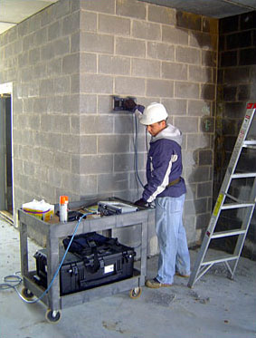 Surface Penetrating Radar Testing of a Reinforced Concrete Masonry Wall |
The output from the SPR system can be used to identify conditions in the masonry. Radar signals are processed by a mobile computer and displayed in real time on the screen as a series of bands. The shade of the band is a function of the phase and amplitude of the reflected signal. Based on the shades and shapes of the reflected signals, three basic conditions within a grout space can be detected:
- Void in Grout Space: Air inside a grout space reflects the signal as the wave passes through the masonry at the air interface. The resulting reflection (as illustrated in this publication) from masonry to air is displayed as a black-white-black band.
- Reinforcing Bar Embedded in Grout Space: Since steel objects are perfect reflectors, the reflection from a reinforcing bar is always inverted and displayed as a white-black-white band. The shape of the band is that of a hyperbola, due to the discrete diameter of the bar and reflection of the signal as the antenna passes over the bar.
- Grout Filled Grout Space, No Reinforcement: The dielectric constant of grout and masonry are very similar. Therefore, the reflection of the wave at the grout/masonry interface will have a low amplitude and appear as a gray shade.
The characteristics of the wave reflection also permit calculation of the depth of embedded steel reinforcement relative to the surface of the antenna. The SPR method, however, cannot be used to directly determine reinforcing bar diameters from the reflected wave. At left, Figure 1 illustrates representative SPR output from the survey of a reinforced concrete masonry column.
Under favorable conditions, the SPR signals can be used to determine approximate splice lengths of bars when the bars are placed side by side, relative to the line of the antenna scanning direction. The perfect reflection of the wave and the characteristic hyperbola shape of the steel reflection hides materials directly behind the steel object so that they are not detectable by this method.
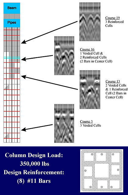 Figure 1: SPR Survey Results of a Reinforced Masonry Column |
Infrared Thermography
IRT uses the principles of thermal energy absorption, transmission and emission to distinguish between hollow and grout-filled cells in masonry. Since this method can only differentiate between hollow and solid masonry cells (steel cannot be detected), it is often coupled with a pachometer survey or SPR survey to locate and evaluate reinforcement installation. Detailed information, such as positioning of reinforcement and splice lengths, cannot be determined with IRT alone.
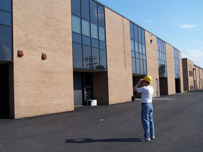 Infrared Thermography of a Masonry Building |
An infrared camera detects these minute differences in emitted thermal energy. As a result, when viewed with an infrared camera, hollow cells are displayed in a sharp and distinct contrast to grouted cells. In examples in this publication, cells that are not grout-filled appear as lighter gray shades.
Thermal sources can include the sun (solar energy) or an artificial heat source, such as a heater or heat lamp. Optimum conditions for IRT testing occur when there is a combination of both, such as testing an air-conditioned building in the summer on a hot sunny day. In this example, the exterior masonry surfaces are exposed to solar energy and develop high exterior temperatures, while the interior masonry surfaces are exposed to lower-conditioned interior air temperatures. The thermographic image would thus display hollow cells as hot (as they emit the thermal energy) and the solid grouted cells as cool (as the energy is transferred through the wall).
A sample photograph from IRT is illustrated in Figure 2 below. Note the hollow cells appear white (hot), while the solid cells appear black (cold). In this example, the thermographer can rapidly and easily assess the grout placement, particularly the grout voids and misalignment of grouted cells. With the use of a camcorder linked to an infrared camera, survey data can be recorded, taped and printed with ease for use in evaluating conditions.
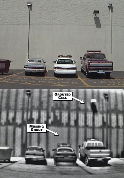 Figure 2: IRT Survey Results of a Reinforced Wall |
Selecting the Best Test Method
No single test method is applicable for all conditions and all construction types, and often several methods combined with selective destructive testing is required to evaluate a problem.
SPR testing is often limited by voids or air spaces within construction. The signal will not penetrate air spaces in typical masonry cavity wall construction; therefore, the method is often limited if access to the back-up wythe is not available.
Likewise, IRT is very dependent on the thermal conditions of the element being tested. If a sufficient thermal gradient cannot be developed across the component, IRT will be ineffective.
It is advisable to plan for some destructive testing to verify the results obtained from the nondestructive testing method selected. Probe openings will be required to calibrate equipment to accurately assess concrete cover depth. Probe openings are also required to verify reinforcement bar sizes, which cannot be determined nondestructively through the methods discussed.
Summary
Nondestructive test methods can be extremely valuable in the assessment of masonry structures, permitting the collection of more comprehensive data than could be collected through destructive testing alone. The test methods discussed can also be used for quality assurance testing and inspection of work in progress, as well as verifying as-built conditions of existing structures.
About the Author
Gerald A. Dalrymple, P.E., is a principal of Whitlock Dalrymple Poston & Associates Inc. in Manassas, Va., a consulting engineering firm that specializes in evaluation, repair and restoration of existing structures. As a principal at WDP, Dalrymple is involved in the evaluation and repair of existing masonry and concrete structures suffering from water penetration, corrosion damage and material failures. His primary duties include repair design, bid solicitation and construction administration of full-scale repair programs. He can be reached via e-mail at adalrymple@wdpa.com, or by calling 703-257-9280.
Gerald Dalrymple, P.E., is providing two educational sessions during the MCAA Masonry Showcase, being held in Las Vegas, March 29-31. "Non-Destructive Test Methods for Masonry" is Thursday, March 30, from 9-10:30 a.m., and "Commercial Masonry Problems & Solutions" will be held on the same day from 10:45 a.m.-12:15 p.m. For more information or to register for this industry event, visit www.masonryshowcase.com.


