Flushing Out Flashing Basics
By Joshua J. Summers, SE, PE, Kami Farahmandpour, PE, RRC, RWC, CCS, CCCA

Flashing is a crucial component in modern masonry walls. Whereas solid, multi-wythe masonry walls — mostly constructed before the 1900s — manage water infiltration through absorption and evaporation, modern masonry walls must accommodate moisture penetration by providing a collection and drainage system. This system consists of flashing and weeps. Flashing also serves to prevent water penetration at interfaces with other building systems, such as windows and other penetrations.
Cavity wall design recognizes that water penetration through masonry is inevitable, and it provides the necessary means to manage moisture. Flashing location, material selection, detailing and proper installation are all significantly important to ensure that water does not penetrate to the interior areas of buildings.
Once moisture has penetrated through the exterior veneer of the masonry wall, it will begin flowing down the interior face of the veneer. Where the vertical flow of water is interrupted by a horizontal surface, water has the potential to penetrate to the interior areas of a building. Such interruptions typically occur at wall bases, shelf angles, lintels, slab edges, through-wall penetrations and windowsills. These are the primary locations where flashing is necessary to manage water.
Flashing also is used at other locations to prevent moisture penetration, more so than managing water after penetration. This is typically the case at coping stones on parapet walls and at the head and jambs of windows.
It should be noted that most model building codes, including the 2000, 2003 and 2006 versions of the International Building Code (IBC), require installation of flashing at various areas of masonry walls. The specific locations where flashing is required in each version of the IBC have changed slightly over the years; however, the intent remains the same.

The most durable flashing materials are sheet metals — typically copper and stainless steel. These materials are resistant to punctures, corrosion and water absorption. However, installation is somewhat more difficult than for flexible materials, since they require shop or field bending prior to installation. Another factor is the sealing of laps and joints, which normally is accomplished by soldering the sheet metal sections together. Sheet metals also tend to be the most expensive flashing materials.
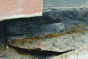
One of the most common materials used for flashing is rubberized asphalt. It typically comes in variable width sheets and is self-adhesive. The sheets are manufactured through careful blending of rubberizing agents with asphalt (typically SBS or SEBS). The rubberized asphalt then is laminated with a backing material, usually high-density polyethylene. These products are usually 40 mils thick, are flexible, easy to install, non-corrosive, and will not absorb water. They are a somewhat less durable than sheet metal since they are more susceptible to punctures. However, since this type of flashing often is fully adhered to the substrate, a puncture will not necessarily result in a leak. Nonetheless, punctures should not be tolerated in any kind of flashing installation. Laps and joints in rubberized asphalt flashing materials are sealed through the self-adhesive properties of the material.
Thin — approximately 20 mils thick or less — polyethylene sheeting (plastic) also is being used as flashing. However, this is not a durable material. In such thicknesses, polyethylene has nearly no puncture resistance and will degrade over short periods of time. Additionally, sealing joints and laps in thin polyethylene or other types of plastic sheets is difficult.
There are many other types of through-wall flashing products such as laminated copper sheets. Before specifying any flashing materials, they should be evaluated for their durability and installation practicality.
Flashing accessories such as termination bars, drip edges, solder, primers, adhesives and sealants must also be durable and compatible with flashing and other wall materials. Metal components must be non-corrosive and sealants must remain soft and flexible. No material should adversely affect any other material within the wall system.

Detailing flashing to collect and divert water from the interior cavity wall surfaces to the exterior should consider the following:
- End dams must be used at the ends of each length of non-continuous flashing to force water to the exterior of the masonry cavity walls. The most common location for end dams is at the ends of window lintels and windowsills. Without them, water will flow along and off of the end of the lintel into the wall cavity (path of least resistance). However, since the window lintel spans the full width of the wall cavity, water can spill into the cavity at or near the interior walls, exposing them to potential water penetration.
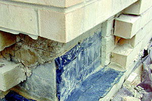
- Proper detailing at corners is necessary to ensure moisture does not penetrate through the flashing system. Details for corners must indicate locations for seams and laps. Corner details may include the use of preformed sheet metal, even if rubberized asphalt flashing is used.
- Flashing must extend through the full thickness of the wall and terminate beyond the face of the wall with a drip edge. Terminating flashing within the exterior wythe of masonry could allow water to travel back beneath the flashing, into the cavity, and possibly back to the interior wythe of the wall system. Use of self-adhesive rubberized asphalt flashing should include separate, stainless steel drip edges adhered directly to lintels and shelf angles, beneath the self-adhesive flashing. This is because rubberized asphalts will degrade with UV exposure. Therefore, when used with a stainless steel drip edge, the rubberized asphalt does not need to extend beyond the face of the exterior wall.
- The interior vertical leg of flashing should extend up a minimum of eight inches. The top edge of the flashing must be terminated properly. The two most common termination methods are embedment in a bed joint of the masonry backup or with a termination bar. Termination bars should be fairly stiff to provide a uniform clamping force between the fasteners and resist bending during installation. A "[" shape often is best for this purpose. Termination bars should also be corrosion resistant.
- Details of seams should include a minimum lap length of four inches. Although metal flashing often is soldered at the seams, sometimes it is better to adhere the lapped areas with flexible sealant. This will accommodate thermal expansion and contraction where soldered seams will not.
- Flexible flashing must be fully supported across the full width of the wall cavity below. At shelf angles and lintels this is always the case. However, flexible flashing placed at floor lines without shelf angles will form a trough over the width of the cavity if supplemental support is not provided. This trough will retain water and can cause large leaks where there are any small imperfections in the flashing seams. Water will then flow through the seams, into the cavity space below and possibly down the face of the interior wythe, exposing interior areas of a building to water penetration. Supplemental support typically is provided through installation of a sheet metal angle attached to the masonry backup wythe and spanning across the full width of the cavity.
- Penetrations through flashing materials, such as at coping stone anchors, must be detailed to ensure the penetration is watertight. Most often, this is accomplished with a flexible sealant or mastic.
- Weeps must be placed in the mortar joint immediately above the flashing at a maximum of 24 inches on center. In general, the larger the weeps, the better. Cell vents installed in head joints, typically the same size as a head joint, will quickly remove more water than cotton rope or small plastic tube weeps.
Although not specifically the topic of this article, it is important to note that flashing cannot serve its intended purpose if the wall cavity is too narrow and not kept clean during construction. For cavity walls to function as intended, they must be designed with a minimum inch-inch wide cavity. This dimension is considered the minimum width necessary, as recommended by the Brick Industry Association, to prevent the cavity from being bridged by mortar or other materials and to allow water to cross over to the interior wythe. Narrower cavities are far more difficult to keep clear during construction. However, it should be noted that mortar bridging can still occur with a wider cavity if the masons do not exercise care to keep the cavity clear during construction.
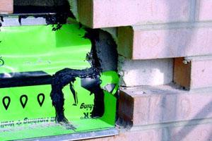
In addition, be aware that a weather-resistive barrier (WRB) is required by all three versions of the IBC. A WRB also can serve as a vapor retarder and/or an air barrier depending on its properties. Design and installation of flashing for masonry cavity walls will require close coordination between WRB installers and flashing installation crews as these two components will serve as parts of the moisture management system within the wall assembly. Proper placement of the air barrier, WRB or a vapor retarder within the wall assembly deserves a long discussion, worthy of its own article.
- Materials must be supplied and installed as specified by the design professional. Use of poor-quality materials cannot be allowed.
- All seams, joints and corners must be lapped and sealed thoroughly.
- Full support for flexible flashing must be installed.
- When using self-adhesive flashing, all surfaces to which the flashing will be adhered must be cleaned and primed. During cold weather, heat guns may be required to ensure proper adhesion.
- Flashing installation should be sequenced to avoid damage until it is fully protected within the wall cavity. Flashing often is installed in the bed joints of CMU backup materials and left hanging for several months until the exterior brick is installed. This practice leaves the flashing highly susceptible to damage from wind and construction activities, and should be avoided.
- The wall cavity must be kept clean of mortar and other materials that will bridge the gap between the exterior and interior masonry wythes and clog weeps. Without a clean cavity and clean weeps, the flashing system will not be able to serve its intended purpose.
About the Authors
Joshua J. Summers is a principal structural engineer at Building Technology Consultants, PC. Summers has evaluated and developed repair designs for numerous masonry building components. These projects have included both solid- and cavity wall construction with brick, CMU, terra cotta, limestone and clay tile materials.
Kami Farahmandpour is the principal of Building Technology Consultants, PC. His expertise is concentrated in the evaluation and repair of building envelopes, including various types of exterior walls, waterproofing systems and roofs. Among his many professional activities, he has served a three-year term as an associate director of the Sealant, Waterproofing and Restoration (SWR) Institute. He also is the co-author of A Practical Guide to Weatherproofing of Exterior Walls, developed by SWR Institute.


