June 16, 2009 8:25 AM CDT

Seismic building code requirements have been a part of masonry construction for many years. Until the mid- to late-1980s, few seismic requirements existed for masonry joint reinforcing, anchors and ties. But thinking started to change in the late-1980s and early- to mid-1990s, when model codes introduced new provisions that improved the performance of masonry structures during earthquakes.
Today, designers have seismic design categories A – E (Figure 1), which define the degree of protection provided to the public against the potential hazards due to earthquakes. The seismic design categories are based on the expected level of seismicity in a geographic area and the type of building. For example, seismic design category A has the least risk of an earthquake and few additional design requirements, while E is required to meet the strictest seismic design provisions in order to minimize risk of failure during an earthquake.
The vast majority of designers use the International Building Code (IBC), which adapted the ACI 530 Code for Building Code Requirements for Masonry Structures. In ACI 530, designers use Chapter 6, titled Veneer, for general and seismic design applications for masonry construction. In the veneer application, the backup system is designed to carry the entire load with no load requirements for the veneer.
Starting with seismic design categories A and B, ACI 530 has no additional requirements than the normal general requirements for joint reinforcing, anchors and ties.
Seismic design category C is also exempt from any additional joint reinforcing or tie requirements, except where the designer allows the backup system and veneer to share the load. In this rare brick masonry case, the structure is required to have a continuous single wire, minimum 9 gauge (W1.7) at a maximum spacing of 18 inches on center vertically. The continuous wire must be mechanically attached to the backup system by way of adjustable anchors with clips or hooks. The continuous wires are required to provide ductility and post cracking strength.
Seismic design categories D, E and F require continuous wire, minimum 9 gauge, in the veneer at a maximum spacing of 18 inches vertically. The required clips and hooks provide a channel for the continuous wire to lay in the bed joint and transfer the load to the backup system. Since their inception, seismic design categories E and F required these provisions, but not until 2006 was seismic design category D included, after a major modification by the IBC.

With the new seismic requirements in design categories D, E and F, the masonry joint reinforcing industry had a new challenge in developing a line of products for seismic applications.
Charlotte, N.C.-based Wire-Bond spent countless hours working on ways to attach a channel part or clip to the end of their adjustable double hook. The part would also need to accommodate a continuous 9-gauge wire, and not exceed one-half the thickness of the mortar joint, normally 3/8-inch thick. The company tried plastic snap-on pieces, but height was a problem in the joint, and it added an extra step for the mason by having to install an extra part. With spacing at 16 inches on center horizontally and vertically, costs of the system increased significantly in labor and parts with the plastic piece. Wire-Bond also tried welding continuous straight and cut wire to the hook, but the welding accuracy could not be achieved to meet the ACI 530 specification.

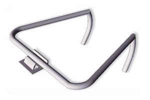
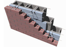
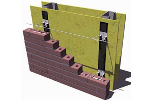
A welded metal clip that provided a continuous channel was the answer. The Wire-Bond welded clip consists of a 14-gauge, flat steel part with a lip that is tack welded to the back of the 3/16-inch adjustable hook (Figure 2). The curled lip holds the continuous wire in place in the bed joint of the veneer. The clip is hot-dipped galvanized along with the wire part (in this case, a hook), keeping only galvanized steel in the bed joint, a commonly accepted material in the mortar joint. The adjustable hook is part of a frequently used adjustable level eye joint reinforcing system used in multi-wythe walls (Figure 3). The adjustable hook is also used with Wire-Bond’s RJ-711 plate system (Figure 4) for steel stud brick veneer applications, so the company could solve two common seismic design applications with one part.
When the Wire-Bond welded seismic clip system was first introduced in the market, the company received a favorable response from both designers and mason contractors. The designer now had a new option for masonry seismic applications that was of the highest quality, economical and code compliant. The mason contractor viewed the welded seismic clip as user friendly, saving time and money: a one-piece, adjustable hook that tied the backup system to the veneer and provided a channel in the bed joint to lay the additional wire required to meet seismic requirements.

As the popularity of the product grew, Wire-Bond started seeing it specified along the coast line, where structures are sometimes designed to meet wind loads of 140 mph, plus. From independent lab testing in tension and compression, the company has found that its seismic load values can easily meet hurricane wind requirements.
Wire-Bond pleasantly found from developing the seismic clip that it solved seismic applications for numerous types of backup systems. Basically, any type of wire connector could be converted to seismic compliant by welding of the metal clip and the use of continuous wire in the veneer.
From a manufacturing standpoint, Wire-Bond made the clip user friendly and economical. The company achieved the ultimate goal of reducing the cost of the wall by eliminating any additional labor costs to the mason contractor. Everyone wins when the cost of masonry walls is kept economical.
Connectors, Anchors and Fasteners
Solving seismic requirements for masonry joint reinforcing, anchors and ties
By Mike Ripley

Figure 1. Seismic design categories define the degree of protection provided to the public against the potential hazards due to earthquakes.
Today, designers have seismic design categories A – E (Figure 1), which define the degree of protection provided to the public against the potential hazards due to earthquakes. The seismic design categories are based on the expected level of seismicity in a geographic area and the type of building. For example, seismic design category A has the least risk of an earthquake and few additional design requirements, while E is required to meet the strictest seismic design provisions in order to minimize risk of failure during an earthquake.
The vast majority of designers use the International Building Code (IBC), which adapted the ACI 530 Code for Building Code Requirements for Masonry Structures. In ACI 530, designers use Chapter 6, titled Veneer, for general and seismic design applications for masonry construction. In the veneer application, the backup system is designed to carry the entire load with no load requirements for the veneer.
Starting with seismic design categories A and B, ACI 530 has no additional requirements than the normal general requirements for joint reinforcing, anchors and ties.
Seismic design category C is also exempt from any additional joint reinforcing or tie requirements, except where the designer allows the backup system and veneer to share the load. In this rare brick masonry case, the structure is required to have a continuous single wire, minimum 9 gauge (W1.7) at a maximum spacing of 18 inches on center vertically. The continuous wire must be mechanically attached to the backup system by way of adjustable anchors with clips or hooks. The continuous wires are required to provide ductility and post cracking strength.
Seismic design categories D, E and F require continuous wire, minimum 9 gauge, in the veneer at a maximum spacing of 18 inches vertically. The required clips and hooks provide a channel for the continuous wire to lay in the bed joint and transfer the load to the backup system. Since their inception, seismic design categories E and F required these provisions, but not until 2006 was seismic design category D included, after a major modification by the IBC.
New Seismic Products

Figure 2. The Wire-Bond welded clip.
Charlotte, N.C.-based Wire-Bond spent countless hours working on ways to attach a channel part or clip to the end of their adjustable double hook. The part would also need to accommodate a continuous 9-gauge wire, and not exceed one-half the thickness of the mortar joint, normally 3/8-inch thick. The company tried plastic snap-on pieces, but height was a problem in the joint, and it added an extra step for the mason by having to install an extra part. With spacing at 16 inches on center horizontally and vertically, costs of the system increased significantly in labor and parts with the plastic piece. Wire-Bond also tried welding continuous straight and cut wire to the hook, but the welding accuracy could not be achieved to meet the ACI 530 specification.

Figure 3. The adjustable hook is part of a frequently used adjustable level eye joint reinforcing system used in multi-wythe walls.
When the Wire-Bond welded seismic clip system was first introduced in the market, the company received a favorable response from both designers and mason contractors. The designer now had a new option for masonry seismic applications that was of the highest quality, economical and code compliant. The mason contractor viewed the welded seismic clip as user friendly, saving time and money: a one-piece, adjustable hook that tied the backup system to the veneer and provided a channel in the bed joint to lay the additional wire required to meet seismic requirements.

Figure 4. The adjustable hook is also used with Wire-Bond’s RJ-711 plate system for steel stud brick veneer applications.
Wire-Bond pleasantly found from developing the seismic clip that it solved seismic applications for numerous types of backup systems. Basically, any type of wire connector could be converted to seismic compliant by welding of the metal clip and the use of continuous wire in the veneer.
From a manufacturing standpoint, Wire-Bond made the clip user friendly and economical. The company achieved the ultimate goal of reducing the cost of the wall by eliminating any additional labor costs to the mason contractor. Everyone wins when the cost of masonry walls is kept economical.
About the Author
Mike Ripley is National Sales Manager for Wire-Bond.


