Water in the Walls

A Practical Guide to Wall Drainage and Flashing Installation
When a discussion begins regarding cavity wall drainage, flashing or adhered veneer drainage, most of the time it begins with the saying, “Masonry leaks.” Well, yes, masonry does leak, but the systems in place to support the building envelope can prevent the water from entering the substrate, living space or surrounding building materials, thereby preventing any saturation that can lead to further problems.
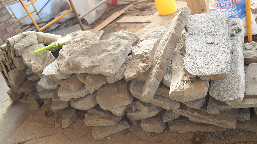
There are many types of wall profiles today and many materials to choose from when discussing drainage. However, the wall that most of us construct is the cavity wall, which can be veneered with terra cotta; natural, cast or precast stone; brick; Concrete Masonry Units (CMU) or composite materials. There are also the popular adhered veneer walls, which typically are veneered with natural stone, cementous decorative stone or tile (see Fig. 1). With the two basic styles of construction come two different methods for drying and draining of the systems.
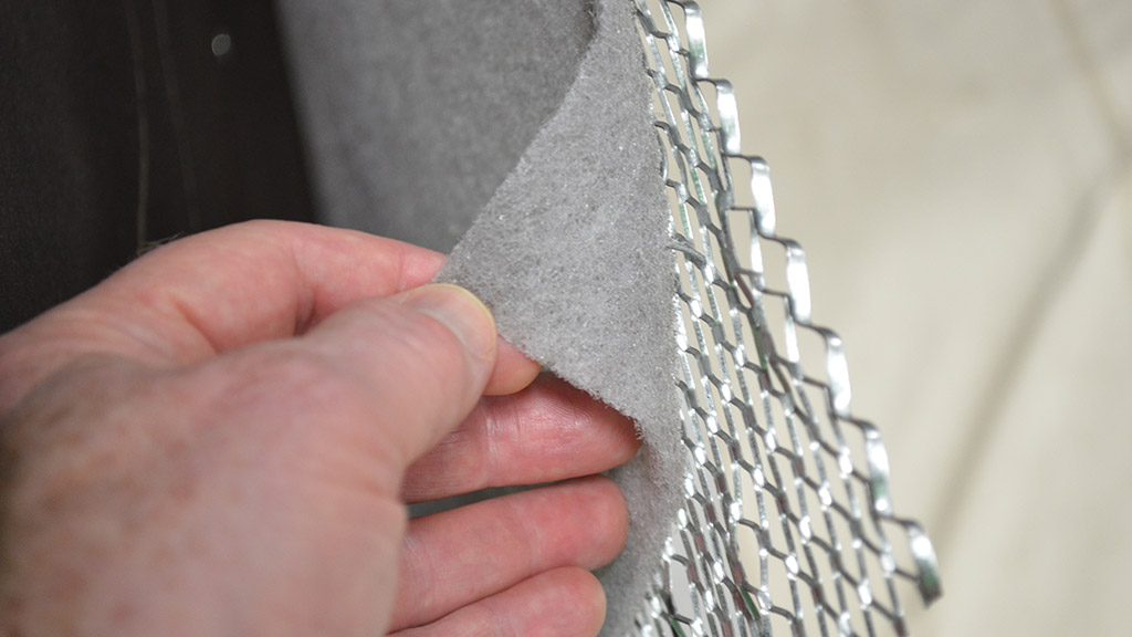
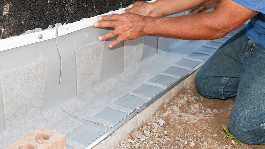
Adhered veneers currently fit a wide range of wall types — from stucco to thin brick, cultured stone or natural stone veneers. In some cases, an exterior insulation finishing system (EIFS) can be added as a system that can benefit from a drainage plane. Many of us have been in the industry long enough to have worked through the evolution of the adhered masonry veneers. Us old guys know the early struggles that have been improved upon. One of the newer changes in adhered masonry veneer walls is the addition of the drainage planes between the air barrier, or the weather resistant barrier and the scratch coat (Fig. 2). The drainage plane is addressed by ASTM International and The Masonry Veneer Manufacturers Association, which is under the umbrella of the National Concrete Masonry Association, with recommendations for installation and details. The drainage planes are simple to install and in some cases can eliminate the second layer of weather resistant barrier required by most current codes. The drainage plane offers a cavity wall feature (adding an air space between masonry veneer and structure) to the adhered veneer that allows drainage of moisture that has penetrated through the veneer; from here the water will drain down to a weep screed away from the structure.
In the late 1960s, copper flashings became widely recognized for their importance. In the 1970s they became mainstream and more popular, as the thin copper foil attached to a fabric with a solvent-based adhesive became the standard. This was a product used by many in the masonry industry, and it is still performing well to this day.
With flashings becoming more of a standard, detailing became important and new products entered the market. In the 1980s, air barriers became part of the National Building Code of Canada, and a section was created that addressed “Wind, Water and Vapor Protection.” Open head joints in brick veneer were filled with tubes and cotton ropes, and finished masonry was cleaned using “detergents,” as acid was on its way out. Even with all of the changes we have seen, the techniques for installing many of today’s products have stood the test of time and are still part of the craft.
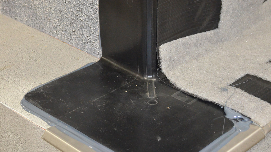
Installing flashing is as important to a well-functioning veneer as full head joints or proper tooling. Flashings at the grade level should be installed above grade and below the finished floor. When a footing is used, this is typically not a problem to accomplish, but with the wide use of turned-down slabs, flashings often have to be placed on the finished floor. This is not desirable, but it is not necessarily a problem if you apply two beads of butyl sealant under the flashing to prevent moisture from travelling under the flashing to the living space. The butyl may not prevent excessive water events like flooding, excessive snow thaw or direct application of exterior sprinklers, but it will prevent a majority of moisture-related issues. When a flashing is stepped down to accommodate grade changes, there are several ways to accomplish this economically. A common method is to extend the flashing on the high side of the grade change 18 inches past the step down. A flashing placed typically two to six courses of brick lower or one to two courses of CMU lower would then begin at the base of the step down and continue following the footing, creating an overlap that would catch water and drain it effectively.
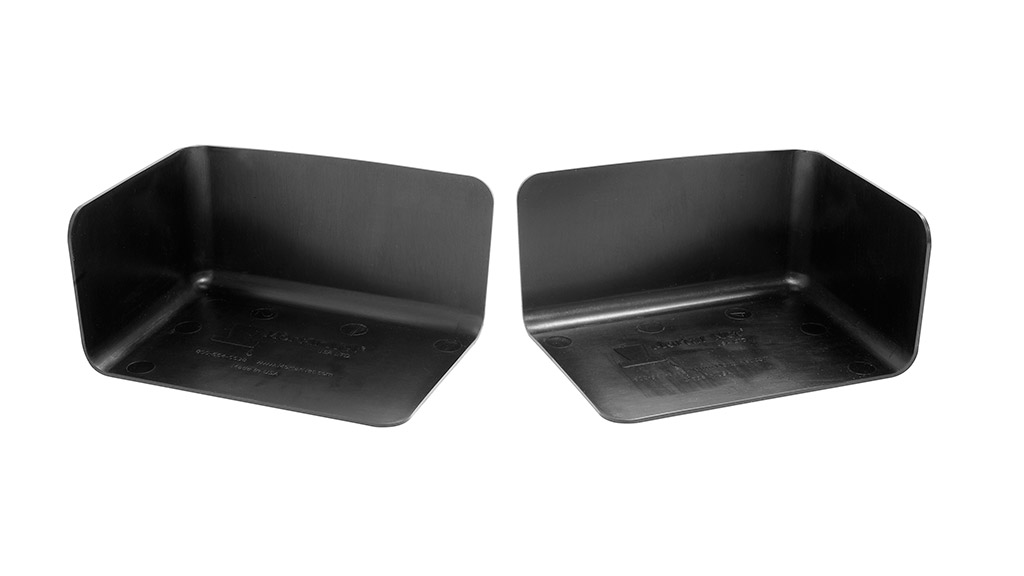
When installing end dams, it is important to first set the end dam directly on the brick shelf and against the substrate wall in a bed of sealant. Two beads are usually enough. The bond of the veneer (head joint location) must be considered prior to setting the end dams, as they typically extend within 1/4 inch of the face of the wall into the head joint.
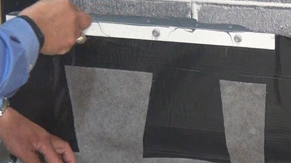
There are many types of membranes available for flashing installations today — far too many to discuss. However, the methods are similar and the process is generally the same. It is important to understand the product you are installing in advance of the installation. Rubberized asphalt is not much fun to install in high winds; unitized flashings (Fig. 5) are easier to install when a drip edge and a term bar are factory installed; and termination bar anchors do make a difference. When installing flashing, unless you are installing prefabricated panels, install the product in sections you can work with in the environment you are placed in. For instance, when working on a third-floor scaffold, shorter pieces of flashing around scaffolding are much easier to work with because they are less cumbersome, whereas longer pieces can easily be placed when installing flashing on grade. Flashing should always extend to the face of the masonry and up the substrate approximately 10 inches (depending on local codes). A bead of sealant should be placed parallel with the face of the wall about 3/4 inch in on the brick shelf to avoid moisture penetration below the flashing. When flashing is cut short of the face of the veneer, water can find its way into the cores of the brick veneer. Then, in the case of a masonry opening, that will lead to water damage on the inside jambs’ heads.
Termination bars need to be attached snugly, but not so tightly that they create deflection in the termination bar. Termination bars should be attached at every metal or wood stud. Intermediate screws will not benefit you, as they can pop out over time and create a “fish mouth” that will cause leaks. When anchoring into a concrete or a CMU backup, a pilot hole must be drilled. Always check the recommended hole diameter, as it is critical to the proper application of your anchors. I personally recommend using a screw-type anchor to mount termination bars, as the self-drilling screws work with wood stud, metal stud and can work with the properly drilled pilot hole. They can also be loosened if placed too tightly.
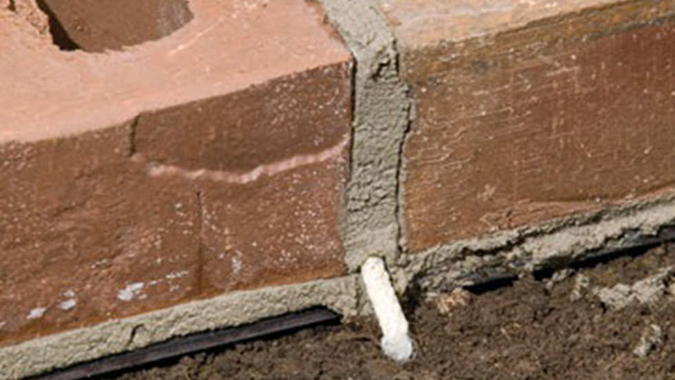
Depending on your geographical location, weeps can be a big part of the discussion. I have seen open head joints in brick work, cotton wicks (Fig. 7), plastic tubes, polyester mesh, plastic cell vents, and metal and plastic vented inserts. What is really important is to use weeps at least every 24 inches, and more under special conditions. I do not recommend cotton wicks or plastic tubes, as in many places the plastic tubes become clogged or they were never properly installed flat on the top surface of the flashing. Cotton wicks tend to deteriorate to black mush, which will not allow for drainage for a number of years. Weeps are available in colors that can closely match the mortar that your client selects; it makes a positive but subtle difference in a nice veneer. Weeps can also be installed at the top of the veneer, either at the soffit or the brick shelf on a multi-story building. The additional weeps allow the cavity of the veneer to exhibit the chimney effect, where the heat of the veneer draws the moisture in the cavity up and out of the uppermost weeps.
Application of spray foam to the exterior of the substrate is becoming more common in many parts of the country, and there seem to be a few schools of thought on this process. The spray foams have proprietary formulas with compatibility requirements. Flashings applied to spray foam must have a sealant and membrane approved by the foam manufacturer. This information is easy to obtain, and flashing and sealant products are readily available across the country. We frequently see flashing being applied prior to foam insulation because the foam contractor does not have to make another pass on the wall to seal over the termination bar.
Flashing materials on most projects are typically specified by the architect or designer. Contractor preference for products can be evaluated during the submittal process, where compatibility issues are typically addressed for the entire project. Most manufacturers work hand in hand to determine compatibility between each company’s products and will offer letters of support to the contractors or architects.
The rebirth of the industry after the economic slowdown of the past few years is still in its infancy, and we have to train personnel on tasks both old and new. Flashings have many new innovations in membranes, parts and pieces, and even unitized premade and precut flashings. But the bottom line is that, no matter what product you choose, the basic steps for installation remain industry standards. They are proven by the test of time, just like masonry itself.
About the Author
Steven Fechino is engineering and construction manager with Mortar Net Solutions, makers of TotalFlash and BlockFlash. For more information, call 800-664-6638, or visit www.mortarnet.com.


