October 16, 2008 9:01 AM CDT

Units of Autoclaved Aerated Concrete (AAC) are most commonly laid using thin-bed mortar and can be used for bearing-wall masonry. Design provisions for AAC masonry are given in the MSJC Code, and construction requirements are given in the Masonry Standards Joint Committee (MSJC) Specification. In this article, the manufacture of AAC is briefly reviewed; practical examples of AAC masonry construction are illustrated; MSJC design provisions for AAC masonry are summarized; and practical construction guidance for AAC masonry is emphasized.
Autoclaved Aerated Concrete (AAC) is a lightweight, concrete-like material with many small, closed internal voids. Material specifications for AAC are prescribed in ASTM C1386. AAC typically weighs one-sixth to one-third as much as conventional concrete, and is about one-sixth to one-third as strong. It is suitable for bearing walls and shear walls of low- to medium-rise structures. Its thermal conductivity is one-sixth or less that of conventional concrete, making it energy efficient. Its fire rating is slightly longer than that of conventional concrete of the same thickness, making it useful in applications where fire resistance is important. Because of its internal voids, AAC has low sound transmission, making it useful acoustically.
In the United States, modern uses of AAC began in 1990 for residential and commercial projects in the Southeastern states. U.S. production of plain and reinforced AAC started in 1995 in the Southeast and has since spread to other parts of the country. A nationwide group of AAC manufacturers was formed in 1998 as the Autoclaved Aerated Concrete Products Association (AACPA, www.aacpa.org). Design and construction provisions for AAC masonry are given in the MSJC Code and Specification. The AACPA includes one manufacturer in Monterrey, Mexico, and many technical materials are available in Spanish. AAC is approved for use in Seismic Design Categories A, B and C by the 2007 Supplement to the International Building Code, and in other geographic locations with the approval of the local building official.
AAC can be used to make unreinforced, masonry-type units, as well as factory-reinforced floor panels, roof panels, wall panels, lintels, beams and other special shapes. This article addresses primarily masonry-type units only.
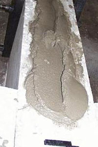
Steel molds are prepared to receive the fresh AAC. If reinforced AAC panels are to be produced, steel reinforcing cages are secured within the molds. After mixing, the slurry is poured into the molds. The expansive agent creates small, finely dispersed voids in the fresh mixture, which increases the volume by about 50 percent in the molds within three hours.
Within a few hours after casting, the initial hydration of cementitious compounds in the AAC gives it sufficient strength to hold its shape and support its own weight.
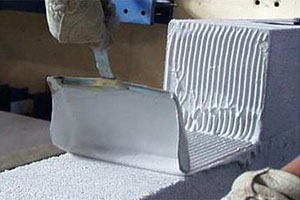
After cutting, the aerated concrete product is transported to a large autoclave, where the curing process is completed. Autoclaving is required to achieve the desired structural properties and dimensional stability. The process takes about eight to 12 hours under a pressure of about 174 psi (12 Bars) and a temperature of about 360ºF (180ºC), depending on the grade of material produced. During autoclaving, the wire-cut units remain in their original positions in the AAC block. After autoclaving, they are separated for packaging.
AAC units are normally placed on pallets for shipping. Unreinforced units are typically shrink-wrapped, while reinforced elements are banded only, using corner guards to minimize potential localized damage that might be caused by the banding.
Many different types of exterior finishes are available. Polymer-modified stuccos, paints or finish systems are the most common exterior finish for AAC. They increase the AAC's water-penetration resistance, while allowing the passage of water vapor. Heavy acrylic-based paints containing aggregates are also used to increase abrasion resistance. There is generally no need to level the surface, and horizontal and vertical joints may be chamfered as an architectural feature, or may be filled.
Masonry veneer may be used over AAC masonry in much the same way that it is used over other materials. The veneer is attached to the AAC masonry wall using special masonry ties. The space between the AAC, and the masonry can be left open (forming a drainage wall), or can be filled with mortar.
When AAC panels are used in contact with moist or saturated soil (for example, in basement walls), the surface in contact with the soil should be coated with a waterproof material or membrane. The interior surface should either remain uncoated, or be coated with a vapor-permeable interior finish.
Many different types of interior finishes are available. Interior AAC wall panels may have a thin coat of a mineral-based plaster to achieve a smooth finished surface. Lightweight interior gypsum-based plaster may provide a thicker coating to level and straighten walls, and to provide a base for decorative interior paints or wall finishes. Interior plasters have bonding agents to enhance their adhesion and flexibility, and are commonly installed by either spraying or troweling.
When applied to the interior surface of exterior AAC walls, gypsum board should be attached using pressure-treated furring strips. When applied to interior walls, moisture-resistant gypsum board can be applied directly to the AAC surface.
For commercial applications requiring high durability and low maintenance, acrylic-based coatings are often used. Some contain aggregates to enhance abrasion resistance.
When ceramic wall tile is to be applied over AAC, surface preparation is normally necessary only when the AAC surface requires leveling. In such cases, a Portland cement- or gypsum-based parge coat is applied to the AAC surface before setting the ceramic tile. The ceramic tile should then be adhered to the parged wall using either a cement-based thin-set mortar or an organic adhesive. In moist areas such as showers, only a Portland cement-based parge coat should be used, and the ceramic tile should be set with cement-based, thin-set mortar only.
Using Autoclaved Aerated Concrete Correctly
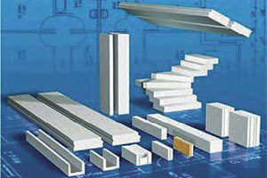
Examples of autoclave aerated concrete elements. Image courtesy of Ytong International.
Autoclaved Aerated Concrete (AAC) is a lightweight, concrete-like material with many small, closed internal voids. Material specifications for AAC are prescribed in ASTM C1386. AAC typically weighs one-sixth to one-third as much as conventional concrete, and is about one-sixth to one-third as strong. It is suitable for bearing walls and shear walls of low- to medium-rise structures. Its thermal conductivity is one-sixth or less that of conventional concrete, making it energy efficient. Its fire rating is slightly longer than that of conventional concrete of the same thickness, making it useful in applications where fire resistance is important. Because of its internal voids, AAC has low sound transmission, making it useful acoustically.
History of AAC
AAC was first produced commercially in Sweden in 1923. Since that time, its production and use have spread to more than 40 countries on all continents, including North America, Central and South America, Europe, the Middle East, the Far East and Australia. This wide experience has produced many case studies of use in different climates and under different building codes.In the United States, modern uses of AAC began in 1990 for residential and commercial projects in the Southeastern states. U.S. production of plain and reinforced AAC started in 1995 in the Southeast and has since spread to other parts of the country. A nationwide group of AAC manufacturers was formed in 1998 as the Autoclaved Aerated Concrete Products Association (AACPA, www.aacpa.org). Design and construction provisions for AAC masonry are given in the MSJC Code and Specification. The AACPA includes one manufacturer in Monterrey, Mexico, and many technical materials are available in Spanish. AAC is approved for use in Seismic Design Categories A, B and C by the 2007 Supplement to the International Building Code, and in other geographic locations with the approval of the local building official.
AAC can be used to make unreinforced, masonry-type units, as well as factory-reinforced floor panels, roof panels, wall panels, lintels, beams and other special shapes. This article addresses primarily masonry-type units only.
Materials Used in AAC
Materials for AAC vary with manufacturer and location, and are specified in ASTM C1386. They include some or all of the following: fine silica sand; Class F fly ash; hydraulic cements; calcined lime; gypsum; expansive agents such as finely ground aluminum powder or paste; and mixing water. AAC masonry units have no internal reinforcement, but can be reinforced at the jobsite with deformed reinforcement placed in vertical cells or horizontal bond beams.How AAC is Made
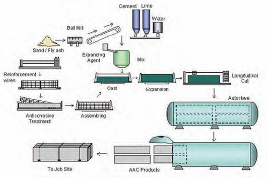
To make AAC, sand is ground to the required fineness in a ball mill, if necessary, and is stored along with other raw materials. The raw materials are then batched by weight and delivered to the mixer. Measured amounts of water and expansive agent are added to the mixer, and the cementitious slurry is mixed.Steel molds are prepared to receive the fresh AAC. If reinforced AAC panels are to be produced, steel reinforcing cages are secured within the molds. After mixing, the slurry is poured into the molds. The expansive agent creates small, finely dispersed voids in the fresh mixture, which increases the volume by about 50 percent in the molds within three hours.
Overall steps in manufacture of autoclaved aerated concrete.
Within a few hours after casting, the initial hydration of cementitious compounds in the AAC gives it sufficient strength to hold its shape and support its own weight.
After cutting, the aerated concrete product is transported to a large autoclave, where the curing process is completed. Autoclaving is required to achieve the desired structural properties and dimensional stability. The process takes about eight to 12 hours under a pressure of about 174 psi (12 Bars) and a temperature of about 360ºF (180ºC), depending on the grade of material produced. During autoclaving, the wire-cut units remain in their original positions in the AAC block. After autoclaving, they are separated for packaging.
AAC units are normally placed on pallets for shipping. Unreinforced units are typically shrink-wrapped, while reinforced elements are banded only, using corner guards to minimize potential localized damage that might be caused by the banding.
AAC Strength Classes
AAC is produced in different densities and corresponding compressive strengths, in accordance with ASTM C1386. Densities and corresponding strengths are described in terms of "strength classes" (See Table 1).| TABLE 1 - AAC Strength Classes | |||
| Strength Class | Specified Compressive Strength, lb/in2 (MPa) | Nominal Dry Bulk Density, lb/ft3 (kg/m3) | Density Limits, lb/ft3 (kg/m3) |
| AAC 2.0 | 290 (2.0) | 25 (400) 31 (500) | 22 (350) - 28 (450) 28 (450) - 34 (550) |
| AAC 4.0 | 580 (4.0) | 31 (500) 37 (600) | 28 (450) - 34 (550) 34 (550) - 41 (650) |
| AAC 6.0 | 870 (6.0) | 44 (700) 50 (800) 44 (700) 50 (800) | 41 (650) - 47 (750) 47 (750) - 53 (850) 41 (650) - 47 (750) 47 (750) - 53 (850) |
Typical Dimensions of Masonry-type AAC Units
Typical dimensions for masonry-type AAC units (masonry-type units) are shown in Table 2 below.| TABLE 2 - Dimensions of Masonry-type AAC | |||
| AAC Unit Type | Thickness, in. (mm) | Height, in. (mm) | Length, in. (mm) |
| Standard Block | 2 - 15 (50 - 375) | 8 (200) | 24 (610) |
| Jumbo Block | 4 - 15 (100 - 375) | 16 - 24 (400 - 610) | 24 - 40 (610 - 1050) |
Typical AAC Masonry Applications
AAC masonry can be used in a wide variety of structural and non-structural applications. For example, in applications used in projects in Arizona and Las Palmas, Mexico, the thermal and acoustical efficiency of the AAC makes it an attractive choice for a building envelope.Structural Design of AAC Masonry
AAC masonry is designed according to the provisions of Appendix A of the MSJC Code (MSJC 2008), referenced by model codes throughout the United States. Design of AAC masonry is similar to strength design of clay or concrete masonry and is based on a specified compressive strength. Compliance with that specified compressive strength is verified by compressive strength testing of AAC cubes, using ASTM C1386, when the masonry-type elements of AAC are fabricated. Extensive practical guidance on design with AAC masonry is provided in the 5th edition of the Masonry Designers' Guide (MDG 2007).Combinations of Flexure and Axial Load
AAC masonry is designed for combinations of flexure and axial load using the same principles as for the strength design of clay or concrete masonry. Nominal capacity is computed assuming plane sections, tension steel at yield, and an equivalent rectangular compression block.Leveling bed and shims for first course of AAC masonry units — the first course of AAC masonry units is laid on a leveling bed of ASTM C270 Type M or S mortar, using wedges (if desired) to plumb and level the units.
Bond and Development of Reinforcement
Reinforcement in AAC masonry consists of deformed reinforcement placed in grouted vertical cores or bond beams and surrounded by masonry grout. Development and splice requirements for deformed reinforcement in grout are identical to those used for clay or concrete masonry. Conservatively, the AAC material is not considered when calculating cover for splitting resistance.Shear and Bearing
As with clay or concrete masonry, the shear resistance of AAC masonry is computed as the summation of a shear resistance due to the AAC itself, and a shear resistance due to reinforcement oriented parallel to the direction of the shear. Because conventional bed-joint reinforcement produces local crushing of AAC under cross-wires, the MSJC Code requires that only the shear contribution of bond beams with grouted reinforcement be considered. To prevent local crushing of the AAC, nominal stresses in it are limited to specified compressive strength. When floor or roof elements bear on AAC walls, shear failure of the edge of the wall is also possible. This is handled by limiting the shear stress on potential inclined failure surfaces.Laying AAC Masonry Elements
At diaphragm levels, AAC masonry walls are connected to the floor or roof using a grouted bond beam, similar to clay or concrete masonry construction. After laying the AAC masonry units, the plane of the wall can be smoothed using a sanding board made for this purpose.Laying AAC masonry units using thin-bed mortar and toothed trowel — subsequent courses are laid using a polymer-modified, thin-bed mortar, applied with a special toothed trowel.
Electrical, Plumbing Installations in AAC
Electrical and plumbing installations in AAC masonry are placed in routed chases. Care should be taken when laying out chases to ensure that the structural integrity of the AAC elements is maintained. Do not cut reinforcing steel or reduce the structural thickness of the AAC elements except where permitted by the designer. In vertically spanning AAC elements, horizontal routing should be permitted only in areas with low flexural and compressive stresses. In horizontally spanning AAC elements, vertical routing should be minimized. When possible, it may be advantageous to provide designated chases for large quantities of conduit or plumbing.Exterior Finishes for AAC
Unprotected exterior AAC deteriorates when exposed to cycles of freezing and thawing while saturated. To prevent such freeze-thaw deterioration, and to enhance the aesthetics and abrasion resistance of AAC, exterior finishes should be used. They should be compatible with the underlying AAC in terms of thermal expansion and modulus of elasticity, and should be vapor permeable.Many different types of exterior finishes are available. Polymer-modified stuccos, paints or finish systems are the most common exterior finish for AAC. They increase the AAC's water-penetration resistance, while allowing the passage of water vapor. Heavy acrylic-based paints containing aggregates are also used to increase abrasion resistance. There is generally no need to level the surface, and horizontal and vertical joints may be chamfered as an architectural feature, or may be filled.
Masonry veneer may be used over AAC masonry in much the same way that it is used over other materials. The veneer is attached to the AAC masonry wall using special masonry ties. The space between the AAC, and the masonry can be left open (forming a drainage wall), or can be filled with mortar.
When AAC panels are used in contact with moist or saturated soil (for example, in basement walls), the surface in contact with the soil should be coated with a waterproof material or membrane. The interior surface should either remain uncoated, or be coated with a vapor-permeable interior finish.
Image courtesy of Aercon Florida.
Interior Finishes for AAC Masonry
Interior finishes are used to enhance the aesthetics and durability of AAC. They should be compatible with the underlying AAC in terms of thermal expansion and modulus of elasticity, and should be vapor permeable.Many different types of interior finishes are available. Interior AAC wall panels may have a thin coat of a mineral-based plaster to achieve a smooth finished surface. Lightweight interior gypsum-based plaster may provide a thicker coating to level and straighten walls, and to provide a base for decorative interior paints or wall finishes. Interior plasters have bonding agents to enhance their adhesion and flexibility, and are commonly installed by either spraying or troweling.
When applied to the interior surface of exterior AAC walls, gypsum board should be attached using pressure-treated furring strips. When applied to interior walls, moisture-resistant gypsum board can be applied directly to the AAC surface.
For commercial applications requiring high durability and low maintenance, acrylic-based coatings are often used. Some contain aggregates to enhance abrasion resistance.
When ceramic wall tile is to be applied over AAC, surface preparation is normally necessary only when the AAC surface requires leveling. In such cases, a Portland cement- or gypsum-based parge coat is applied to the AAC surface before setting the ceramic tile. The ceramic tile should then be adhered to the parged wall using either a cement-based thin-set mortar or an organic adhesive. In moist areas such as showers, only a Portland cement-based parge coat should be used, and the ceramic tile should be set with cement-based, thin-set mortar only.
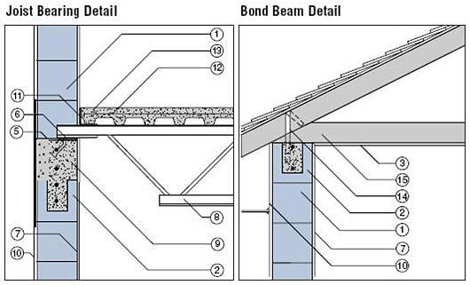
Typical Construction Details for AAC Elements
A wide range of construction details for AAC masonry is available on the Web sites of individual manufacturers, accessible through the Web site of the AACPA.About the Author
Richard E. Klingner, Ph.D. is the L. P. Gilvin professor of civil engineering at the University of Texas at Austin, where he specializes in the behavior and design of masonry, particularly for earthquake loads. He is also the author of Masonry Structural Design and the former chair of the Masonry Standards Joint Committee (MSJC).


